Representing an object of the space in a plane by giving the illusion of the third dimension is a real challenge!
|
|
|
|
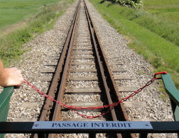
| On a drawing in perspective (or a picture, here the railway of bay of the Somme - France), parallel lines contained in a plane parallel to the front plane are parallel , but other parallel lines converge on a vanishing point F on the horizon line h. | In parallel perspective all real parallel lines are also parallel on the drawing (vanishing point at the infinity). | |
To depict some line (neither parallel nor perpendicular to the frontal plane) we must determine two of its points or one of its points and its direction (a parallel line). Let's notice that the representation of a circle is usually an ellipse.
To improve the readability of the representation the hidden parts are drawn with dotted lines.
| Remark: in a parallel perspective distances are preserved in the planes parallel to the frontal plane (F), but there is another plane direction where this property holds: the direction (f') symmetric of the one (f) of the frontal plane with respect to the projection direction (d).
Indeed, among the quadrilaterals with two parallel sides and two sides with same length one finds, besides the parallelogram, the isosceles trapezium and crossed types. To improve your knowledge: La perspective cavalière (Audibert G.) - APMEP 1990 (in French) |
 |
Drawing the section polygon in real size needs a little more work, but remains an elementary exercise. The sides laying in the front and back panes are in real size; the segments laying on vanishing lines have real size double of those appearing on the drawing (for a ratio r=1/2). Thus we can, using constructions of well chosen rectangular triangles, obtain the length of all segments whose ends lay on two perpendicular edges.
To restrict the number of length to construct, we may notice that a section is always either a parallelogram, either a parallelogram truncated by a line (triangle, trapezium, pentagon) or by two parallel lines (hexagon).
exercises: Can the section polygon be an equilateral triangle? a rectangle? a rhombus? a square? a regular pentagon? a regular hexagon?
It is of course advisable to look for answers with arguments before to consult the solutions.
It is important to understand how these two drawings are made; we choose a leak angle α=40° and a reduction ratio k=0.5=1/2.
parallel perspective of a cube with a diagonal plane as frontal plane
Here the frontal plane is imposed; it therefore contains two opposite edges [AE] and [CG] (with length l) and two parallel diagonals [AC] and [EG] of opposite faces of the cube ABCDEFGH. Let us first examine the face ABCD of the cube: its diagonals [AC] and [BD] are perpendicular and have the same midpoint M, thus MA=MB=MC=MD=(l√2)/2. The section rectangle ACGE is seen in real size: l × l√2.
parallel perspective of a regular pentagon
Since the pentagon is a plane figure, its plane can not serve as a frontal plane (no deformation); thus we choose a pertinent orthogonal plane containing an "interesting element", for example one of its symmetry axes; with this choice one side and the opposite diagonal lay in the vanishing direction. |
OH = cosθ ≈ 0,31
OA' = cos(θ/2) ≈ 0,81 HB = HE = sinθ ≈ 0,95 A'C = A'D = sin(θ/2) ≈ 0,59 |
 |
The most easiest is to use four vertices of a cube; we obtain a nice drawing, but not very practical.
Otherwise we use the net (equilateral triangle with its midpoints triangle). The orthocenter H of the base ABC is also center of gravity and orthogonal projection of the vertex S on the plane (ABC). We can easily construct the altitude HS of the pyramid.
| Let us now choose the elements of the perspective: the frontal plane containing [BC] and perpendicular to the plane (ABC), the vanishing direction (the altitude (AK) of ABC is a vanishing line), and the reduction ratio 1/2.
First we construct the altitude HS in real size. Then we place successively b and c (bc=BC), k midpoint of [bc]. On the vanishing line (ka) we place a such as ka=KA/2 and h such as kh=KH/2=ka/3. Finally we have to place s on the line perpendicular to (bc) going through h, such as hs=HS. Exercise: Achieve a drawing using a plane of symmetry (containing an edge and the midpoint of the opposite edge) as frontal plane. |
 |
| H is the orthogonal projection of the vertex S on the base plane (ABC). (MA) is one altitude of ABC. We construct the altitude SH in real size.
[BC] lays in the frontal plane; (AM) and (KH) are vanishing lines.
|
 |
| |||||||||||||||
|
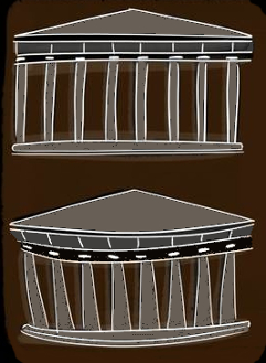
correction of the effects of perspective in architectureThe perspective "distorts", in particular buildings; so that they appear as they are, it must therefore be tricky. The Parthenon is a fine example of the tricks implemented by architects to correct these distortions: • swollen columns and more or less inclined towards the inside, • thicker corner columns, • domed base, treads and pediment curved. The drawing shows the monument as it appears to us and its appearance in the absence of "correction". Each block of stone is therefore unique, cut to the nearest millimeter, according to its place in the building. With the techniques of the time, this feat was achieved in just nine years.
|
 |
home page
 |
convex polyhedra - non convex polyhedra - interesting polyhedra - related subjects | August 1999 updated 25-06-2020 |